This post is meant to both be a chronicle of building a specific custom masonry heater as well as serve as a tutorial for general masonry heater construction details that come up throughout the process.
Here’s the design… it debuts our see-through firebox castings and defines a modern shape that is a departure from the standard vertical configuration often seen in North American masonry heater construction.


Here we are at the beginning. We have gone through a design process, a window has been modified to accomodate the design, and the framers have poured a foundation slab and perfectly reframed the floor. Vertical rebar is stubbed out of the slab at planned locations.

Ruben (of Natural Art Stonework) and I are laying the concrete block foundation.
We have filled the 2" clearance required between the foundation and framing with mineral wool to maintain the insulated plane of the floor system. We have attached the mineral wool with screws and fender washers and will later use it to form our top slab.

Outside air (from the crawl space) is being plumbed to the foundation and some extra blocks have been laid to provide support for the cement board pan for the concrete.

We’re all set to pour the with reenforced posts and top slab of our foundation.
Notice the chalked lines which mark our desired height for the pour to leave room for exactly two layers of calcium silicate board and a final layer of cement board to plane out with the subfloor.

We use a drop-screed to get the slab a consistent depth below subfloor.

We are building up our two layers of calcium-silicate board. This material is refractory, insulative, and has structural compressive strength - a rare combination. It allows the project to preserve the insulated plane of the floor throughout the space rather than having a significant thermal bridge through the foundation.
Now it’s time to lay out the chimney! Lay it out in 2D on the floor plane and then shoot the corners up to the box you will frame in the rafters…


Look at the cross-framing in the rafters and the newly-installed chimney ceiling support box…

And up above…

At least three screws per side for the ceiling support box!
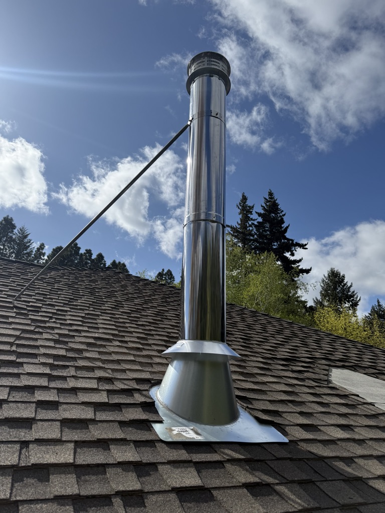
Oh yeah, here’s the view from the roof and the namesake of this model!  …
…

If you’ve come this far, you deserve some more drawings!


Understanding this gas flow diagram is important to understanding the overall design. You can see that the main heat exchange pathway brings the gases down through a small “bell” and then out and back through a heated bench. A bypass damper is installed which, when open, allows the hot gases to go straight to the chimney and provides an easy way to prime the chimney and also relaxed conditions for opening the door and reloading the fire.

Ethan of Columbia Gorge Plaster is training to build masonry heaters!

We begin with the base course of the core. The Outside Air Damper has been installed and the shaft has been extended using the Shaft Extension.

Another course and several things are now defined:
- the ash drawer area
- the interchangeable air exchange pathway between outside air and room air and also between primary air coming up through the grate and the secondary air injected by the air bars.
- two cleanouts on the near side to service the long bench runs
- the entrance and returns into the heated bench.
We dry lay the firebox subfloor to check our positioning and square…

We mortar the subfloor in and install the gasket rope into the gasket channel…

We take a moment to shim the primary air damper with ceramic paper to make sure it is snug and centered so the paddle will travel freely. Notice that I have cut a small diagonal out of the paddle to ensure a small bleed of primary air is always present even when the damper is shut.


The second provided gasket rope is placed along the outside of the damper and then the stainless damper trim is placed to cover the assembly. Make sure to peel any plastic off provided stainless parts like this damper trim and find center on the firebox funnel to match it to center on the subfloor.The firebox funnel is set dry-laid and 1/8" ceramic paper is used to gasket it to the airbars stacked next to it so that they can be removed if the damper below needs servicing.

The Air Bars are set in mortar and any “sploodge” in the air injection slots is left to semi-harden so that it can be removed without smearing them.


Once the Air Bars are set, the outer structural firebrick are laid with care to keep the vertical air distribution slots completely clean and unobstructed by mortar for secondary air flow.


We temporarily clamp the inner and outer walls and dry-lay one of the lintels to set the alignment between walls and lintel. Then we set the other lintel in mortar to lock in the other side before coming back to the first dry-laid one to also set that one in mortar. The matching positive and negative “cleats” allow the lintels to pull the walls into the correct place as we set them on the Air Bars.


With the firebox complete, construction continues on the main part of the masonry heater core which includes the downdrafting bell, the return to the chimney, and they bypass in between them. Notice:
- we have thickened the top of the firebox with splits anticipating quite a bit of heat in that area
- we have wrapped the 8x8 Pivoting Bypass damper in 1/8" ceramic paper to provide a gasket to allow the metal to expand and contract inside the masonry.
- we have used a laser to check our chimney alignment and ground the chimney circle into the capping slabs.


The main part of the core is complete and work is done on “plumbing” the heated bench using 8x12 flue liners. Since the 8x12 flue liners are too large to cut once on a brick saw, after you have flipped the flue liner to set up your second cut, align the first cut along the blade groove in the rolling carriage and also sight the blade beyond the initial cut to ensure your second cut is aligned with with your first. A 14" blade is just short of cutting all the way through with those two cuts and you will likely need to connect/finish them with a grinder.


With the core complete, the expansion joint is installed between the core and facing using a combination of 1/4" ceramic paper around all openings and cardboard. This plane allows the core, which will be the hottest part of the heater, to expand and contract both laterally and vertically without affecting the facing masonry.


Here we are “facing” the heater with 4" concrete block as a substrate for a plaster finish. Notice the trowel in the middle picture making sure there is room for our firebox floor flashing to fit when we later install it. We dilligently run the trowel around the whole opening as it is created to anticipate the 18 ga formed stainless angles we will later be installing there along with ceramic paper to protect our facing material from the intense heat of the firebox. Notice also that we have cut the damper shaft conduits to size and scored them to ensure that the mortar has a good hold on them. We also have shimmed the conduit with some building paper because we prefer for there to be a little extra room above the shaft rather than below. This allows for the heater core to thermally expand vertically without pinching the alignment of the shaft through the facing. We operate the damper (either turning or pulling it) several times during the mortar curing process before finally letting it set in order to ensure that the conduit is in the optimal location.


An interesting part of this project is the sloped backrest which we have created by stepping in our masonry and then using the mortar to fill and screed an angled plane.


The facing is mostly complete. A couple of interesting details to note…
- The cleanout and ash doors have been masked and placed inside of their masonry frames to ensure that the masonry frames do not deform as the facing is set. Care has been taken to make sure that these doors and corresponding frames have been set level and plumb.
- We have placed 1x4s shimmed with an additional layer of Ram board to replicate the flooring that can later be installed into the space we have created to create a clean trimless transition with the finished flooring.


With the facing substantially complete, we install the insulated top cap to keep heat down in the body of the heater. We have lined the portion of the facing that comes above the facing with 1/2" ceramic wool and then made a mix of 6 perlite : 1 hydrated lime and packed it in.


A base coat plaster with embedded fiberglass mesh has now been applied.
We’ll be back in a couple of weeks to cut and install the bench and heater capping stones, connect the chimney, apply the finished lime plaster, and install the hardware.
There are a lot of details and processes to installing a masonry heater. This post has provided information in a chronological manner. Here are some articles for further reading that are topic-based:
- Locating a Masonry Heater in Your Floor Plan
- Masonry Heater Planning Guide
- Masonry Heater Installation Details
- Masonry Heater Foundations
- Outside Air for Masonry Heaters
- The Inspiring Plastered Heaters of L’Esprit du Lieu
- Forum Topic: Lime Plaster for Masonry Heaters
And here are some links if you’re ready to take the next step:
- Order Masonry Heater Core Kits from us!
- Engage our Design Services to get experience on your team!
- View our Masonry Heater Hardware Catalog